Krabi International Airport (KBV) has embarked on an expansion to build a third terminal and extend the aircraft parking aprons and associated infrastructure to increase capacity to 8 million passengers per year.
Construction of the new terminal is ongoing and installation of the new apron pavement is substantially completed.
The total number of aircraft stands will be increased to 20, 14 of which will be multiple parking type capable of accommodating one large (‘Code D/E’) or two smaller (‘Code C’) aircraft.
The current Airport Fuel Depot supplies approximately 60 million litres of jet fuel per year. The fuel is imported by dedicated bridger tankers from PTT Surat Thani fuel depot and delivered to the aircraft by refueller vehicles of 25,000 and 50,000 litres capacity.
Krabi has seen a rapid growth in medium and long haul flights, in particular from Europe, serviced by large (Code E) Aircraft such as Airbus A350 and Boeing 787 Dreamliner aircraft, which require high volume fuel uplifts of 100,000 litres or more.
The current truck based aircraft refueling operations present a limitation in terms of refueling rates, which may impact on aircraft turn-round-times as the air traffic volumes increase further.
PTT have therefore decided to improve overall fueling efficiency by installation of a fuel hydrant system which will enable much higher fueling rates and remove the need for multiple refueller deliveries for the larger aircraft.
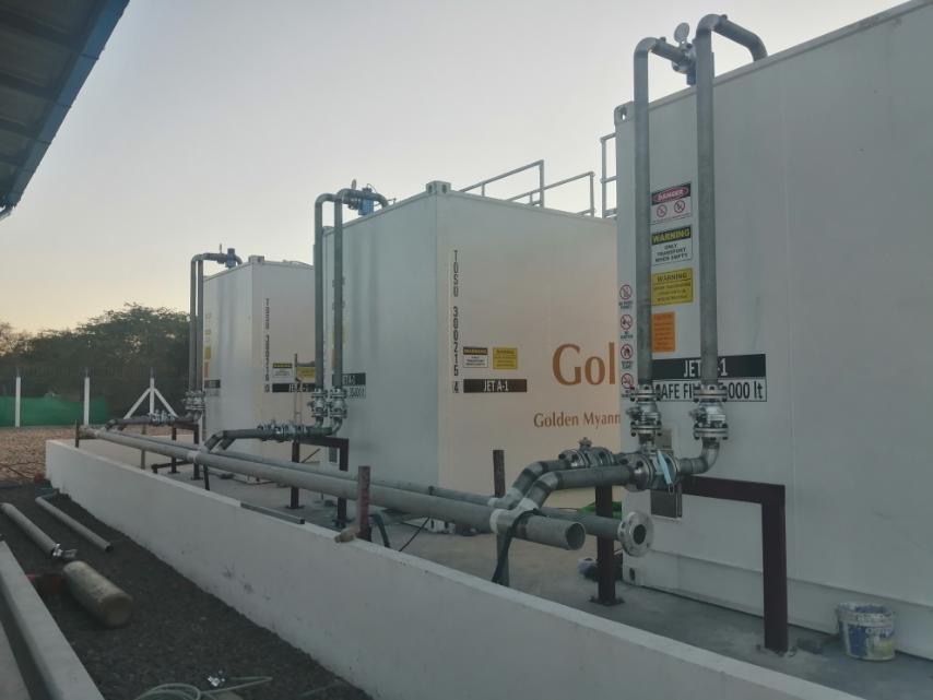
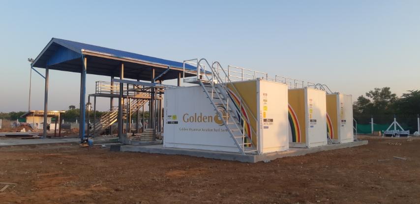
The existing fuel depot will also be expanded and upgraded to supply the fuel hydrant and the increasing fuel demand at the airport.
Brightstar Scope of Work:
The work comprised:
- Review and develop the hydrant design concept
- Compile fuel demand design basis
- Carry out hydraulic calculations to verify hydrant and feeder line sizing
- Review aircraft stand parking positions and verify hydrant fuel point locations
- Develop the FEED Design package for the new Hydrant Fuel System
- Review the existing fuel depot facilities (including ongoing work packages) and identify any modifications and additions required to support the new hydrant fuel system.
- Prepare the scope of works as the basis for tendering and execution of an EPC contract for the hydrant construction and depot modifications.
- Detailed cost estimate for the works
- Prepare preliminary construction method statements for key activities:
- HDD hydrant installation
- Hydrant riser and pit box installation
- Assist PTT in presentations to the Department of Airports in support of their application for a project construction permit
Site visits were carried out to assess the existing depot facilities, ongoing expansion works and to survey the hydrant and feeder line routes and construction methodology.
Value Added:
Hydrant Configuration
A twin parallel 10 inch hydrant configuration was adopted to enable redundancy in operation and flushing capability to maintain fuel cleanliness at the highest standard.
Section valves were installed in chambers to allow isolation of individual sections for maintenance and inspection purposes without disconnecting flow to other sections. The system sizing allowed these valves to be manually operable only, removing the need for power supplies and remote actuation facilities in the valve chambers and reducing cost accordingly, without in any way compromising the safety or operability of the hydrant fuel system.
Operation and Emergency Shutdown of the hydrant system is performed by equipment and control systems located in the airport fuel depot; the only apron side facilities required were the emergency fuel shut off units installed at each aircraft stand, cabling to a marshalling cabinet installed in the Airfield Lighting Room and communications equipment to send the signals by dual redundant fibre optic cables to the fuel depot.
Hydrant Sizing
Detailed passenger throughput forecasts were not available so Brightstar applied ‘reverse’ sizing principles to model hydrant hydraulics. This involved using typical stand utilsation factors, likely apron distribution and aircraft turn round times (TRT) to estimate the peak fuel uplift. This was then input to a preliminary hydraulic model to confirm optimal pipe sizing.
Hydrant Alignment
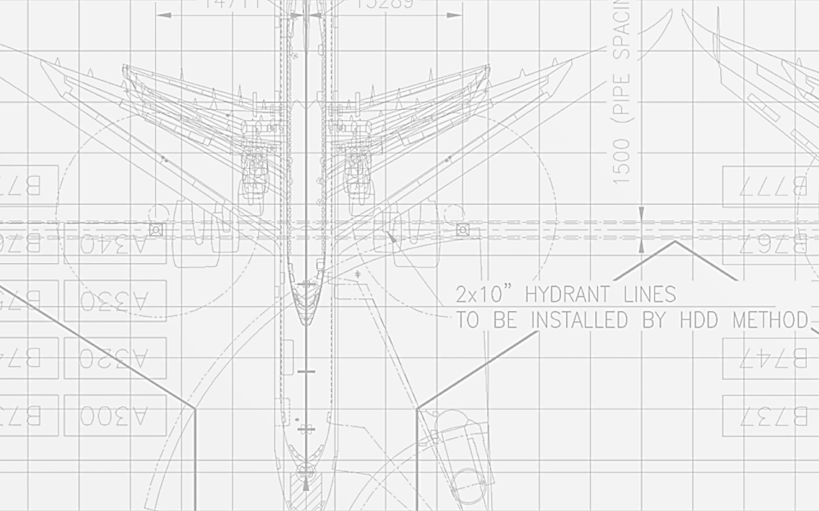
Based on experience from other airports and fuel dispenser operational limitations, Brightstar were able to locate the hydrant lines and all required refueling pits within a straight 4.5 meter corridor along the length of the apron.
This minimized the cost – and disruption – of installing the hydrant pits in the existing apron.
Hydrant Construction
At the time Brightstar were appointed, the construction of the new aprons was substantially complete. Therefore, to minimize the need for intervention in the apron areas, Brightstar developed a methodology for construction of the hydrant beneath aprons by Horizontal Directional Drilling (HDD) technique, using a highly accurate guidance system.
A ‘J-profile’ HDD was adopted in order to maintain the required slope on the finished hydrant, minimize the number of drills required and the depth of the hydrant, in order to facilitate post-drilling the connection of the hydrant risers and pit boxes.
The proposed HDD design also allowed the number of sectioning valve chambers to be reduced to just 3, of which only the central chamber was required to be installed beneath aircraft load bearing apron pavement.
Calculations were also performed to model the ground reaction to the drilling operation beneath the apron; based on this calculation, it was determined that no post-drill grouting or polymer treatment of the soil was required to support the subgrade and apron above.
These engineering measures yielded construction cost savings of around 20%, enabling the project to be delivered within the available budget.
Hydrant Pit Installation
Installing the Hydrant pits and 6 inch riser pipes to the hydrant pipes after HDD was identified as a critical activity to the success of he project.
Brightstar therefore developed a detailed methodology for installation of the risers and pits which the selected EPC Contractor will be required to adopt.
The methodology addresses all the key requirements including:
- Minimise the required area of apron pavement removal
- Safety and fresh air supply in excavated access shaft
- Avoidance of disturbance to the surrounding subgrade
- Field adjustments to the hydrant pit box position and elevation with respect to the surrounding apron finish level.
- Compaction levels for backfill in excess of the requirements from the apron pavement design for subgrade compaction.
Feeder Line Routing
The original concept had been to feed the hydrant by a feed from the depot joining the hydrant at a point part way along the apron.
This would have entailed removal of a large section of newly installed apron to install the connection and the installation of an additional valve chamber in the apron.
To avoid this, Brightstar revised the routing of the feeder lines to connect to the end of the hydrant away from the apron.
This meant that the feeder lines could be installed mostly by open cut construction and no apron removal will be required, minimizing project costs and risks accordingly.


